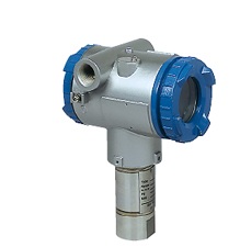


Spool Piece Ultrasonic Flowmeter
Three pairs of sensors for accuracy of ±0.2% of rate
- ・High accuracy
- ±0.2% of rate
Using the new algorithm for calculating the flow velocity, it can measure any type of fluid with high accuracy. - ・Low maintenance
- With no moving parts, FST has long-term stability while requiring only minimal maintenance work.
- ・Bubble resistant
- By using the advanced anti-bubble measurement technology, the interference from air bubbles is greatly eliminated.
- ・Wide temperature range from -40°C to +150°C
- Non conductive fluid including oil, mixed liquid, purified water can be measured.
- ・Easy-to-operate
- with backlit LCD and front panel operation
- ・IECEx, ATEX, NEPSI, and Japanese ex-proof certification
Description
General specifications
| Principle | Transit time difference method with the advanced ABM (anti-bubble measurement) system | |||||||||||||||
|---|---|---|---|---|---|---|---|---|---|---|---|---|---|---|---|---|
| Pipe diameter (mm) | 25, 50, 80, 100 mm 25 mm version is under development. |
|||||||||||||||
| Flow velocity range | Minimum 0 to 0.3 m/s or -0.3 to 0 m/s Maximum 0 to 10 m/s or -10 to 0 m/s |
|||||||||||||||
| Flow range |
|
|||||||||||||||
| Power supply | 100–240 V AC (+10% -15%), 50/60 Hz or 20–30 V DC | |||||||||||||||
| Power consumption | Approx. 20 VA (AC power), Approx. 6W (DC power) | |||||||||||||||
| Varistor | Attached to the power supply terminal | |||||||||||||||
| Surge arrester | Attached to the analog output terminal | |||||||||||||||
| Enclosure | Standard version: IP66 Ex-proof version: IP67 |
|||||||||||||||
| Ambient temperature | Standard version: -40°C to +60°C Ex-proof version: -10°C to +60°C |
|||||||||||||||
| Ambient humidity | ≤ RH 90% | |||||||||||||||
| Ex-proof certification | IECEx, ATEX, NEPSI, Japanese ex-proof standard |
Fluid conditions
| Fluid | Liquid (uniform liquid through which ultrasonic wave can propagate) |
|---|---|
| Bubble content | ≤ 12 vol% |
| Turbidity | ≤ 10,000 mg/L |
| Fluid condition | fully-developed turbulent or laminar flow in a fully-filled pipe |
| Fluid temperature | Standard version: -40°C to +150°C Ex-proof version: -10°C to +150°C |
| Pressure | Up to flange rating |
| Kinematic viscosity | ≤ 100 mm2/s |
Detector
| Wetted parts material | Flow cell: stainless steel 316L Flange: stainless steel 316L Sensor wetted parts: stainless steel 316L |
|---|---|
| Housing | SCS13 |
| Process connections | Flange (horizontal or vertical mounting) |
| Flange rating | JIS10K/JIS20K ANSI 150/300 DIN PN16/40 |
Performance
| Accuracy | ±0.2% of rate (flow velocity: 1 m/s to 10 m/s) ±0.002 m/s (flow velocity: 0.5 m/s to 1 m/s) 4–20 mA DC output: above indicated accuracy ±0.01 mA |
|---|---|
| Response time | 1.2 s (standard) |
Flow transmitter
| Analog output signal | 4–20 mA DC (insulated), 1 point, allowable load resistance: 600Ω or less |
|---|---|
| Contact output | Forward total, reverse total, alarm, acting range, flow switch, or total switch ‧ Type: transistor output (isolated, open collector) ‧ Contact capacity: 30 V DC, 50 mA ‧ 2 points ‧ Normally ON or normally OFF, selectable ‧ Frequency: maximum 100 P/s (Pulse width: 5, 10, 50, 100, 200, 500, 1000 ms) |
| Communication (option) | RS-485 (MODBUS), isolated, arrestor incorporated No. of connectable modules: up to 31 HART (option for ex-proof version) |
| Display | 16-digit 2-line backlit LCD 2-color LED (green: normal, red: at error) |
| Language | Japanese (katakana), English, French, German, Spanish (switchable) |
| Flow velocity/flow rate indication | 8 digits numerals (decimal point is counted as 1 digit) Instantaneous flow rate, instantaneous flow velocity (minus indication for reverse flow) |
| Total value indication | Integrated value of forward flow or reverse flow (reverse flow is indicated with minus symbol) 8 digits numerals (decimal point is counted as 1 digit) |
| Housing material | Aluminum alloy |
| Coating/finish color | Urethane resin/silver |
| Cable entry | Standard version: G1/2 internal thread, with plastic watertight cable glands and rubber plugs Ex-proof version: M20 × 1.5 internal thread, with a) blind plugs or b) cable glands with pressure-proof packings |
| Terminals | Euro-style terminals |
Functions
| Zero point adjustment | By setting zero or clearing zero |
|---|---|
| Damping | For analog output or velocity/flow rate indication, 0 to 100 seconds |
| Low flow cut-off | 0 to 5 m/s in terms of flow velocity |
| Alarm | For hardware error or process error |
| Output burnout (analog output) |
Hold, overscale, underscale, or zero |
| Output limit | High/low limit for analog output is available in the range from 0.8 mA to 23.2 mA |
| Bi-directional range | Forward and reverse ranges configurable independently. Hysteresis: between 0% and 20% of working range Contact output available |
| Auto-switchable two ranges | User configurable Hysteresis: between 0% and 20% of working range Contact output available |
| Flow switch | Contact output available at user-defined H/L limit |
| Total switch | High limit for total flow Contact output can be activated when the total flow has exceeded the high limit. |
| Total preset | Total flow returns to the user-defined preset value every time a user resets the total. |
| Data backup at power outage | On nonvolatile memory |